
Introduction
The gas injection can realize the manufacturing process of complex hollow structures inside die castings. During solidification, the process gas is injected into the foundry to transfer the residual melt into the secondary cavity, thereby forming a predetermined hollow structure.
Influenced by the increasing electrification of road traffic and the objectives of European environmental policy, complex and hollow lightweight components for weight reduction, as well as components with media bearing channels (e. g. thermal control of electric motors) are becoming increasingly important. Previous research successes in transferring gas injection technology from plastic injection molding applications to the die casting process have successfully proved the wide application of this innovative process.
The Basis of Gas Injection Assisted Die Casting Process
The geometric freedom of the casting structure is limited by the process-related conditions of the die casting process. The use of sliders or core pulling can only guarantee the realization of limited functional geometry.
The known gas injection technology in the field of plastic injection molding has been successfully applied to the manufacturing process of functional hollow structures in the die casting process. As with the traditional die casting process, melt dose and mold filling are required in the gas injection process (Figure. 1).
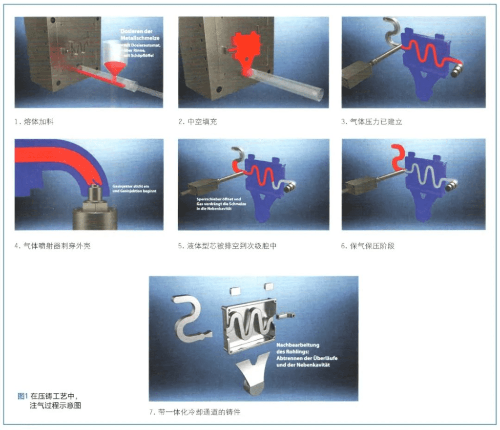
As the die casting solidifies in the die casting mold, nitrogen is introduced into the casting through gas injectors that penetrate the edge shell of the casting. The residual melt still in the liquid state is squeezed into the secondary cavity opened by the gate valve. In this way, a hollow channel can be formed in the casting.
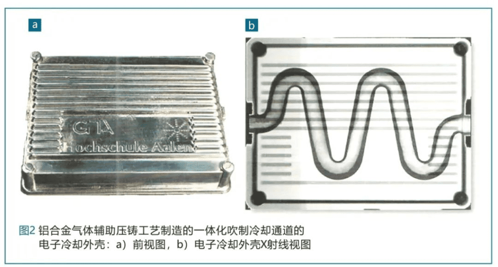
After the casting is formed, the cast metal squeezed into the secondary cavity can be removed in a more economical way. In general, gas injection opens up new possibilities for the product design of media bearing components. As shown in Figures 2 and 3, in the die casting process, media bearing channels can be achieved without losing the core.
In this way, the additional processes with high processing cost after casting can be eliminated. In addition, the risk of leakage can be reduced by reducing the number of joints to be sealed, which is of great added value from the perspective of safety of electrical components.
The length of the curved hollow channel is about 45 cm, which is used for temperature control of electronic housing equipment (see Figure 2). On the outside of the enclosure, the stiffener is installed on the casting, which can increase the heat radiation area.
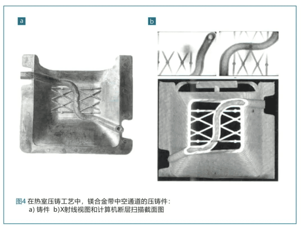
By designing the hollow structure into the component structure, not only the component stiffness can be improved, but also the material can be saved at the same time. Figure 4 shows a demonstrator component made of magnesium, which is reinforced by hollow geometry. This die casting is made by hot chamber process.
In the following example, the cooling channel in the traditional motor housing can be implemented through the two-part structure of the shell. This means that it’s required to carry out some additional processes such as complex machining, welding and sealing. On the other hand, gas-assisted die-casting technology can directly form cooling channels in the die-casting process without complicated additional processes. The joint industrial project with Nemak Europe Ltd. has shown the possibility of integrating cooling channels into an integral motor housing on aluminum die casting (Figure 5).
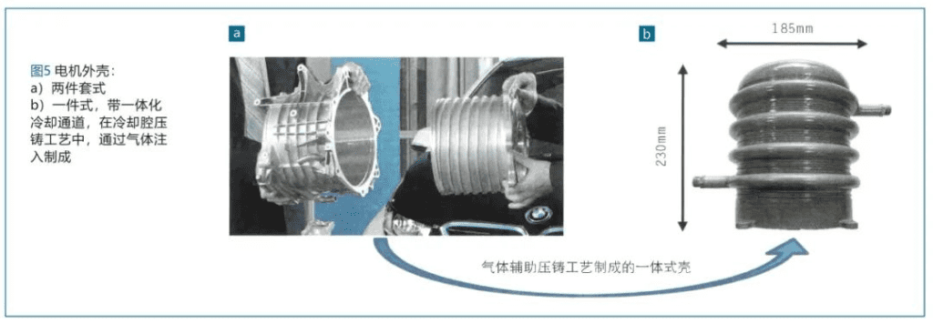
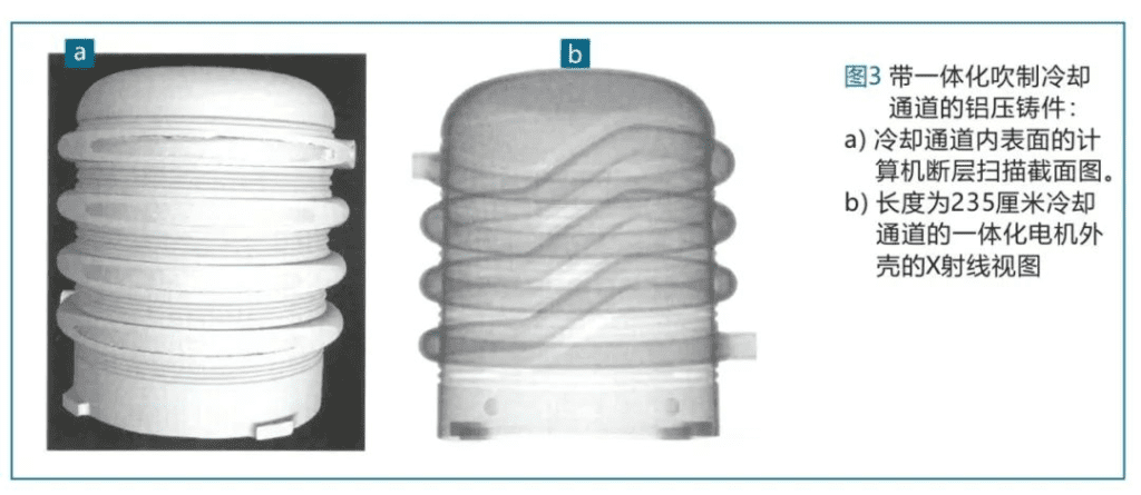
A smooth surface and even wall thickness can be achieved over the entire length of the 235cm cooling channel installed into the motor housing (see Figure 3). With this die casting, the possibility and advantages of the process can become particularly obvious:
– New freedom of product design,
– Manufacture hollow components with complex geometry,
– Replace a multi-part assembly with a single casting,
– Make one-piece castings without sealing and processing after the seam,
– Save additional processes compared to using plugins or losing cores,
-Reduce component costs by saving materials and additional upstream and downstream processes.
Latest Technology Level
In the process shown schematically in Figure 1, the shape of the hollow channel is affected by the external geometry of the casting in the channel area. The high process stability of the MAGIT gas injection process requires a stable die casting process. It is necessary to avoid drastic changes in die casting process factors, because they have a direct impact on the curing characteristics of castings.
In addition to the geometric design of castings and channels, the process and conditions of die casting process described above, the shape of hollow channels is mainly affected by three important parameters of the MAGIT gas injection process:
-The time delay caused by the gas injector injecting gas into the casting,
-The time delay caused by opening the gate valve to release the secondary chamber,
-Gas pressure.
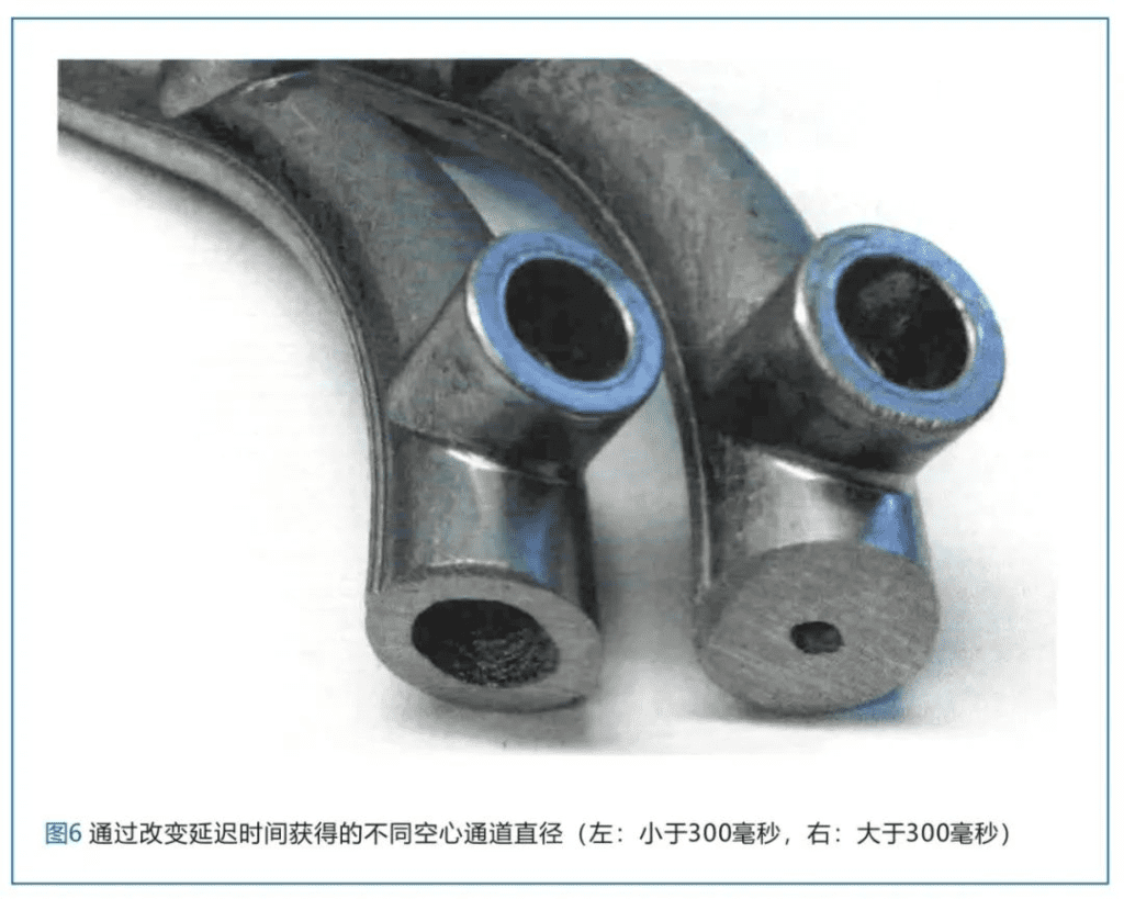
With the change of the delay time, the curing process of the casting continues to move forward. During the gas injection, the thickness of the curing edge layer is also increasing, and the resulting hollow channel will also become smaller (Figure. 6). The MAGIT module provided by TiK can make the gas pressure reach two pressure levels, up to 500 bar.
The first lower pressure level is used to extrude the residual melt in the secondary cavity. After the casting metal is completely squeezed into the secondary cavity, in order to compress and solidify the casting structure again, the gas pressure shall be provided to the second pressure level.
The residual melt zone and the formation of the hollow channel is affected by the casting geometry and the temperature control of die casting mold.
In order to check the feasibility of the MAGIT gas injection process and predict the subsequent structure of the casting hollow channel as early as possible in the structural design stage, curing simulation can be carried out. The research work has shown that the curing simulation results are consistent with the actual geometric shape of the hollow channel in the castings.
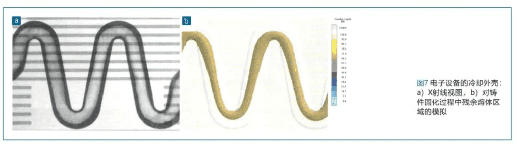
In the casting shown in Figure 7, the X-ray image shows that the central axis of the channel shifted to the internal area (Figure. 7a). In the solidification simulation using the casting software MAGMASoft, this geometric design can be seen with the help of the diagram of liquid composition (Fig. 7b). This is because the mold area is partially overheated when it is internally displaced, which makes the local curing time in these areas longer. During gas injection, the proportion of residual melt is high, so the local wall thickness of the hollow channel formed becomes thinner.
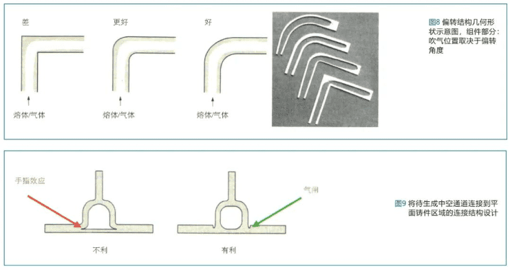
The above effects can also be observed in plastic injection molding technology. The bubbles also deflected towards the inside of the channel and showed asymmetry. In order to achieve the symmetry of bubble position and thus obtain uniform wall thickness, the deflection angle must be increased accordingly (Figure. 8).
When designing castings suitable for the gas injection process, another important structural design angle that must be considered is the correct connection between the plane casting area and the hollow channel to be created (Figure 9). If the connection is improperly designed, the residual melt will appear in the transition area, and the injected gas will also penetrate into the plane area of the casting (Figure. 9a).
In plastic injection molding technology, this effect is known as the finger effect: The finger effect is avoided by reducing the wall thickness in the connection area (airlock, Figure. 9b) to shorten the local cure time and increase the flow resistance in the area.
During the project, the reliability of the simulation results should be demonstrated with various simulator components. So that on the one hand, designers and die-casting workers can check the curing characteristics of the castings that are compatible with the gas injection. On the other hand, the flow technology-related processes in the MAGIT process should be determined in the future, as they are significantly affected by the deflection of the hollow channel to be generated and the design of the combined shape of the cross section transition structure, and will have a direct impact on its quality.
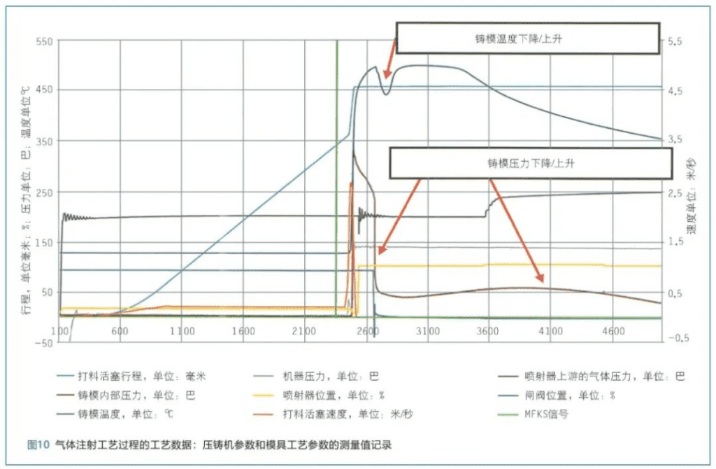
Therefore, the problem points should be determined and identified as early as possible in the structural design stage for optimization. In order to monitor gas injection parameters during production, additional sensor devices are required in the mold (Figure 10). This particularly includes, the gate valves displayed over time and the path of gas ejectors. With the help of these two measurement curves determined by using inductive proximity sensors, the clamping terminals of the gate valve and gas injector and the process conditions due to changes can be immediately identified.
In addition, a target/actual comparison between the intended and actual time delays generated by opening the secondary chamber through the gate valve and spraying the gas through the gas ejector can be achieved. Signals from two metal front contact sensors located in the section area supplied by Electronics GmbH are used as starting signals for a predetermined delay time.
As soon as the cast metals overflow during the die casting process, they send out an electrical signal, which triggers the gas injection process accordingly. Other important measurement variables are the changes of mold internal pressure and mold temperature over time. These measurements are determined by two sensors located in the die casting mold in the area where the hollow channel is to be generated.
The sudden and drastic drop in mold temperature and internal pressure is characterized by the breakthrough of residual melt into the secondary cavity. At this stage of the process, the casting is slightly separated from the die casting mold as the pressure is released.
After the residual melt is completely squeezed into the secondary cavity, gas pressure is formed inside the hollow channel for re-compression. As a result, the casting was pressed onto the surface of the die-casting mold more forcefully, which means that the measured values of the internal pressure and temperature of the mold will rise again.
System technology
To be able to take advantage of the gas injection process in a traditional die casting process, it is generally necessary to use three additional modules and a specified interface for transmitting safety and quality-related process data between the gas injection unit and the die casting machine. In addition to the compact gate valve module consisting of a secondary cavity section plug-in and a locking pin with a hydraulic cylinder, the injection module consisting of a gas ejector and a hydraulic cylinder needs to be inserted into the die casting mold. This includes standard parts with low prices and short lead times. In addition, the components are designed to be assembled and disassembled in a die casting mold in a very short time.
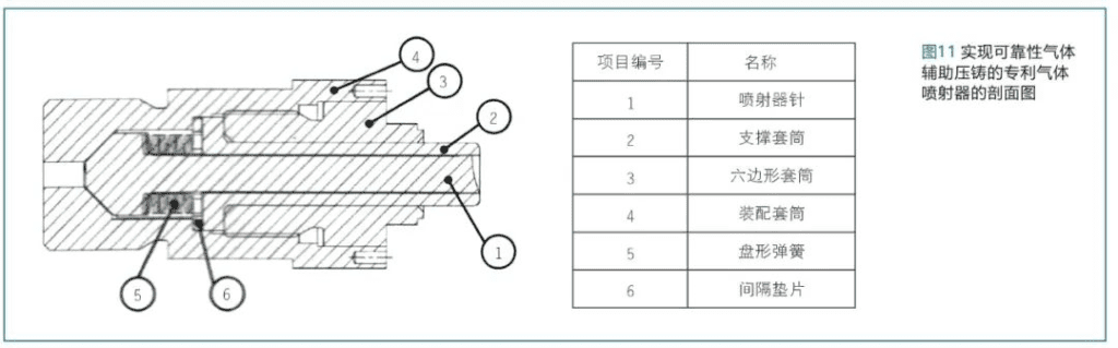
The gas ejector shown in Figure 11 shall be operated by a hydraulic cylinder. The combination of material, injector needle and gate valve spray assembly with corresponding guide sleeve provides a long service life due to its mechanical stability and heat resistance, and can reduce the adhesion tendency of aluminum during die casting.
For maintenance and assembly purposes, insert part of the plug-in into the die casting mold so that it can contact the gas ejector within a few minutes while the die casting machine is in operation. The MAGIT module, shown in Figure 12, occupies a space the size of a European pallet and can be used to provide the supply medium, control and manage the gas injection process, collect and visualize the process data, and achieve coupling with the die casting machine.
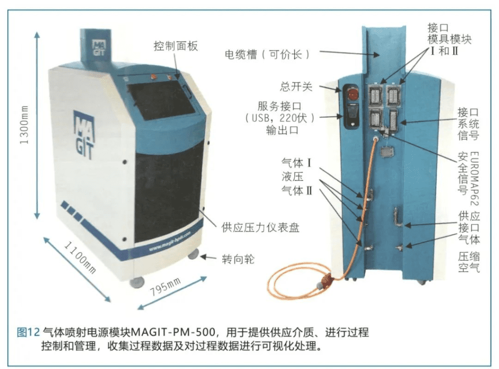
According to mold requirements and customer requirements, the modular structure of the MAGIT power module supports the following equipment options:
Technical device for manufacturing one hollow channel (mold module I) or two hollow channels (mold modules I and II) in a die-casting mold for providing single-stage or multi-stage high-pressure compressor modules with a gas pressure of up to 500 bar, with or without integrated hydraulic unit, for mold modules (gas ejectors and gate valves).
The adoption of the modular structure allows for a high degree of flexibility in equipment options and easy access to components during service and maintenance work. On the front side of the power module, the supply pressure is always visible through the transparent housing.
The optimized operating height and tilt angle of the touch screen enables ergonomic operation. In addition, the detachable control panel allows for position-independent system control. Because of the clear design of the menu navigation, it is easy to achieve intuitive operation in both automatic and manual modes. In addition to the operation menu, there is also a service menu, which can clearly display the signal transmission of each interface, and people can also directly check each system component.
Die Castings Produced By MAGIT
The above MAGIT modules are currently used to produce the following die castings:
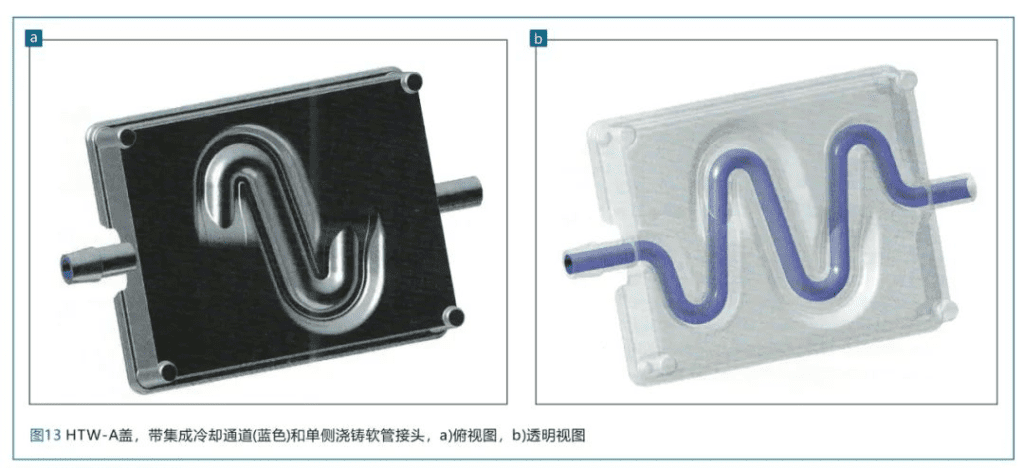
In the shell cover shown in Figure 13, the connection between the circular and semicircular cross section geometry and various connecting structures of the hollow channel and the casting is realized. The curved geometry of the hollow channel results in a longer pipe length and thus better cooling performance.
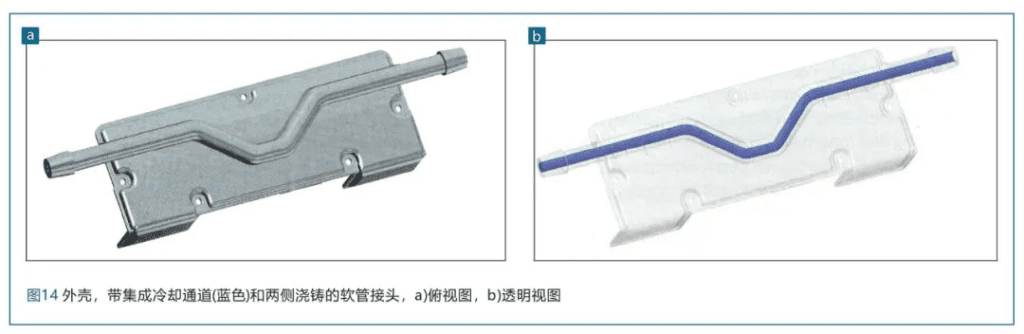
The housing shown in Figure 14 can also be used to cool power electronic components. In addition, a semicircular channel cross section is formed along the surface of the casting.
The die castings produced by MAGIT as shown in Figure 13 and Figure 14 can show the high flexibility of the channel geometry and the saving potential of the gas injection process.
Conclusion
The advantage of gas-assisted die casting is that, on the one hand, it enables new possibilities for component design through functional integration and component replacement. In this way, it can save the time-consuming and laborious additional processes such as machining, connection and compression of individual components.
On the other hand, it enables the flexible design of the component connection position, so that the hose connector can be directly attached to the casting during the die casting process. Therefore, the cost of components can be saved by saving materials and eliminating time-consuming and labor-intensive upstream and downstream processes.
The 36-month MAGIT project focused on bringing the gas-assisted die casting process to market as a process suitable for mass production of hollow lightweight components and media bearing die casting components.