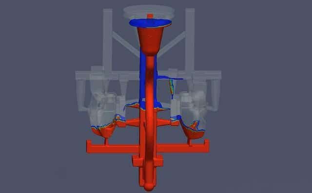
The solidification feeding mode of precision casting is closely related to the location of the internal sprue. Generally, the setting location of the internal sprue shall conform to the solidification feeding mode of the casting.

Principle of Setting Location of Internal Sprue
- For precision castings requiring simultaneous solidification, the internal sprue shall be set at the thin wall of the casting, with a large number and scattered layout, so that the molten metal can quickly and evenly fill the mold cavity and avoid local overheating of the sand mold near the internal sprue.
- For precision castings requiring directional solidification, the internal sprue shall be set at the thick wall of the casting. If there is a feeding riser, it is best to set the riser between the casting and the internal sprue, so that the molten metal can be introduced into the mold cavity through the riser, so as to improve the feeding effect of the riser, such as ductile iron crankshaft, cast steel gear, etc.
- For precision castings with complex structures, the so-called “weak directional solidification” principle of combining directional solidification and simultaneous solidification is often used to arrange the setting location of the internal sprue.
That is, the internal sprue is set for each feeding zone according to the requirements of directional solidification, while the whole casting is filled with multiple internal sprues according to the requirements of simultaneous solidification. This setting can not only let each thick and large part of the casting be fully fed without shrinkage cavity and porosity, but also reduce the stress and deformation to the minimum.
- When the wall thickness of a precision casting varies greatly and it is necessary to set up the internal sprue to introduce molten metal from the thin wall, attention should be paid to the use of cold iron to accelerate the solidification at the thick wall and enlarge the riser. During casting, technological measures such as riser ignition should also be taken to ensure the feeding at the thick wall.
Common Problems of the Setting Location of Internal Sprue
- Due to the coarse grains near the internal sprue, it cannot be set at the areas with high-quality requirements of the casting, and it is best not to set it on the non-machined surface, so as to avoid affecting the appearance quality of the casting. For pipe castings with pressure resistance requirements, the internal sprue is often set at the flange area to prevent shrinkage at the pipe wall.
- The internal sprue shall not directly against the sand mold, sand core, or other weak protruding parts to prevent sand flushing. For castings with the revolved body, the internal sprue shall be introduced tangentially, and the direction shall be consistent so that the impurities are concentrated and discharged into the riser or corresponding process boss.
- The internal sprue shall not be set near the cold iron or core support to avoid reducing the effect of cold iron or causing premature melting of core support.
- The internal sprue shall make the molten metal inject along the mold wall, and do not make the molten metal fall on the surface of the mold wall for a long time to overheat the sand mold locally.
- The setting of the internal sprue shall be conducive to stable mold filling, exhaust, and slag removal. The flow direction of molten metal entering the mold cavity from each internal sprue shall be consistent to avoid being unfavorable to the discharge of slag and gas due to confusion of flow direction.
- For alloys with large shrinkage tendency, such as the cast steel casting, the setting of the internal sprue shall not hinder the shrinkage of the casting, so as to avoid large stress or cracking due to shrinkage obstruction.
- The internal sprue shall be set on the parting surface as far as possible to facilitate the molding operation.
- The setting location of the internal sprue shall be convenient for opening the sandbox, cleaning the casting, and removing the gating system, without affecting the use and appearance of the casting.
- On the premise of meeting the casting requirements, the metal consumption of the casting system shall be minimized, and the size of the sandbox shall be as small as possible to reduce the consumption of molding sand and molten metal.
- The cross-sectional thickness at the junction of the internal sprue and the casting shall generally be less than one-half of the wall thickness of the casting and no more than two-thirds at most. When using the closed casting system, a fractured groove shall be set in the internal sprue to prevent damage to the casting during cleaning.
